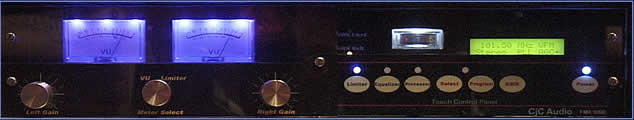
I began the design of a broadcast quality FM stereo transmitter back in 2004. I stripped an old 19 inch rackmount video switcher case to house the transmitter design. This model I designed using an existing FM exciter PLL module which I can control with a separate Microcontroller. The picture below is the front panel of the transmitter. The panel is made of two layers of acrylic with the graphics sandwiched between. Other than the Left/Right level controls and meter select, all other controls are touch cells which detect through the acrylic. This technology was developed by ".Touchsensor Inc. " The small analog meter measures SWR to the antenna which can be switch selected between forward and reflected power. Total RF output power exceeds 1Watt with a 1to1 SWR.
 |
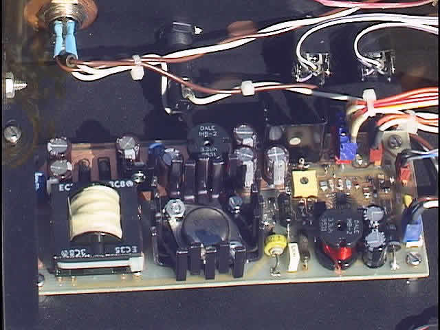
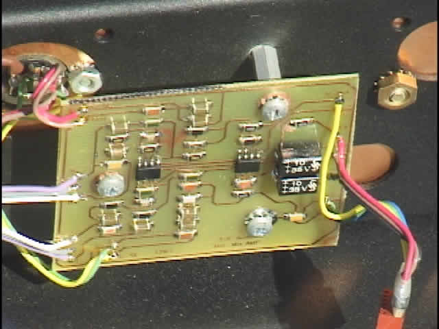
I designed the power supply to operate from a 9 to 20 volt DC input with regulated outputs of +5, +12 and +/-15v. The design is a flyback operating at about 60khz. Shown in the picture below, the switcher is actually good for about 30 watts but I only need about 15 watts to power the entire transmitter.
 |
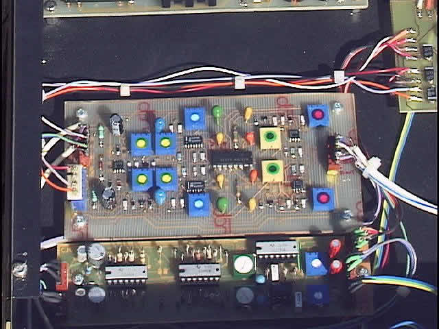
I designed the audio limiter circuit using a Philips NE570 Compandor IC. I created the design surrounding the compandor using low noise op amps, MC33079 which I helped Motorola develop in the late 1980's for low noise audio and telecom use. I use this same design in all my projects when a limiter is needed.
 |
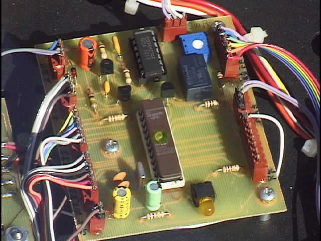
The Microcontroller I used is a Philips 87C751. I didn't need a lot of computing power and I have many of the micros left from old stock. I mainly use the micro for switch debouncing and gate/relay control of the limiter, SWR and the future multiband Compressor/Expandor circuit.
 |
The input balance amplifier is a simple low noise balance to unbalanced converter board with a built in unbalanced mixed input. The unbalanced input connects to left/right phono type connectors and part of a 5 pin din connector. 12v power is also connected to the din which allows for 1 connector to be used to access the rear panel. The balanced inputs are 1/4 TRS jacks also on the rear panel. Audio from this board goes directly to the front level controls.
 |
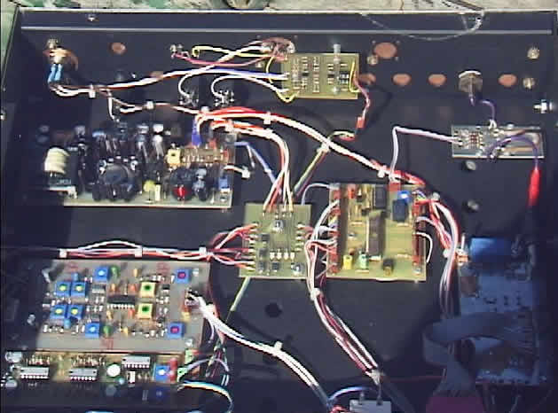
The view below shows the entire transmitter through the acrylic top panel. I have left room for the multiband Compressor/Expandor/Equalizer circuit I have yet to design. I would like to design a circuit to operate similar to the well known "Optimod" circuit used in broadcasting.
 |