Quad Fiber Mux for T1 Circuits
I began my first fiber mux design in 1989 while working at Rockwell International,
Wescom division. My original intention was to mux 5 T1 telecom circuits into
a single mode optical cable interface. At the time, the fiber interfaces were
extremely expensive and had to be designed using discrete components. The
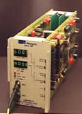
MUX in the photo below is one of two original prototypes I constructed in
my lab at home. I laid out the circuit boards by hand using Leroy reservoir
pens on frosted mylar and creating a negative using Kodalith graphics art
film. I then used a spray resist on blank copper PCB material to expose the
image with ultraviolet light. I mechanically designed the unit to insert into
5 circuit slots of an STS T1 office repeater shelf. The mux functioned well
passing 5 T1's end to end. On this first proto, I had a crude performance
monitoring system, only T1 loss of signal and bipolar error violations for
near and far ends are displayed with LED's on the front panel. This was also
my first design of a switching power supply which I needed to derive my circuit
voltage requirements from the telecom standard of -48 volts. This also gave
me the opportunity to learn 8051 microcontroller code. At this point, the
only problem was getting Rockwell marketing interested. It turns out, Rockwell
was already making plans to sell off the Wescom division so there was no interest
in the project.
| |
 |
|
In
1991 Wescom was sold to Charles Industries. I thought I would give the mux
another try. This time a bit more interest was shown in the marketing department.
I was given the opportunity to prototype a quad T1 version of my original
design. With some help from engineer Carl Ewrite on some FPGA framer work,
we were able to create a fully functional Quad T1 mux. This time with Carl's
framers, we had full performance monitoring capabilities. I used the resources
which were originally for the 5th T1 as overhead. I had near end and far end
performance monitoring capability using two ASCI readouts on the front panel.
The overhead channel was also used for manual loopback of any of the four
T1's. Carl's framers would also allow for inband and ESF loopback .
Again, the company began to lose interest in the project and it was put aside.
I was instead put on factory detail in Casy Illinois troubleshooting production
issues.
| |
 |
|
In 1993 I left
Charles Industries/Wescom to participate in Westell's
newly formed Fiber Optic group. At the time, Westell was developing single
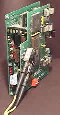
T1 NIU fiber modules. I had already started another quad fiber mux using 400
mechanics. Shown below, I enhanced the design even more by making the design
more compact. I went to a single ASCI readout which could be switch selected
between near end or far end monitoring of the T1 signals. This module required
a second board for the fiber transceivers and T1 channels 3 & 4 . I needed
4 Xilinx 3064 FPGA's on this design in order to get a full ESF framer and loopback
control for each of the 4 T1's. I also designed a switching power supply capable
of a 21 to 56 volt input range. I designed the PCB layout using an old DOS version
of Orcad. The program had many bugs but was able to get some results. The microprocessors
were 87C52's to which I wrote the code in MCS51 assembly format. This first
design definitely had too many micros on it but I didn't have the space for
external ROM, RAM, Buffers, ect. Also, a data buss between boards would have
made for a very large connector pin count between boards.
 |
|
 |
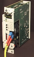
Once Westell
decided to go with ahead with the program, I designed the first production fiber
quad in the 400 mechanics style. Shown below, this model still needed a separate
board for T1 channels 3 & 4. Much of the hardware I used in the prototype
above still remained on the first production board. In order to look ahead to
different types of fiber interfaces, I designed a subassembly with a balanced
transmission line to the main board for transmit and receive of the fiber ECL
signals. This subassembly came in handy later when I designed a WDM single fiber
unit. Another addition to this design was the auto switchover circuitry for
redundant applications. In this application, two cards are mounted side by side
occupying the same four T1 circuits. One module became the master and the other,
the slave. Other features I added, a 115K baud overhead with RS232 interface
which could be used in both directions for overhead communications, outputs
containing performance monitoring information which are sent to an alarm module.
| |
 |
|
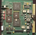
As technology
marched on, I was able to integrate the original four FPGA,s into one. Also,
the program memory of the microcontrollers increased dramatically. This made
it possible to eliminate the entire top board. I added a couple more features
to the board which were never used. One was a jack (J1) which could be used
for overhead options such as an auxiliary POT's service. Another feature, a
switch (S1-6) which was labeled test from the previous unit but I renamed AP.
With this switch enabled at both ends, the far end (CPE) will automatically
be provisioned from the network (COT) side. I created this option so the presence
of a service technician at the customer side would not have to be called for
remote provisioning. As far as I know, this option has never been published.
I believe
Westell
may still be manufacturing the quad fiber. Since the downsizeing in 2002, I
am not sure if the product is still in production.


