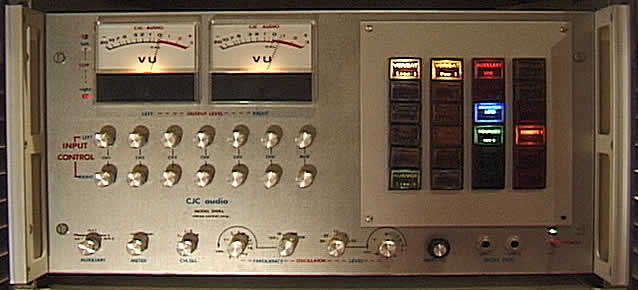
2000A Stereo Preamp
I designed this Mixer/Preamp in the late 1980's. It is still in use today
in my main audio system. My goal was to design the lowest noise preamps as
possible at for the time. I used the MC33078/079 Op Amps I helped Motorola
design in the late 1980's while employed at Rockwell Int., Wescom division.
I specially selected the Op Amps to operate at a full +/-22 volt supply. This
allows for a maximum output voltage swing of nearly 40volts P/P or +25dbm.
The illuminated switches on the front panel drive toggle latches which control
the high voltage analog transmission gates for selecting inputs. Some of the
features include 6 channel mixer plus 1 Aux mix and 1 cascade mix input. The
phono preamp is a balanced direct coupled design operating on +/-22 volts.
The RIAA equalization curve holds within 1% across the frequency range with
a signal to noise near 140db.
| |
 |
|
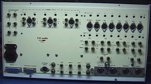
The photo below shows
the back panel of the preamp. I used a combination of 5 pin Din sockets, phono
jacks and XLR. Output calibration trimmers are accessible from the back for
adjustment/calibration from -10db consumer level to +4db broadcast level.
| |
 |
|
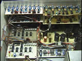
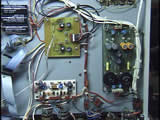
Below are photos of
the interior of the preamp. I designed and wound the power transformer for an
extremely low flux density. I wound the coils on a cardboard tube and then laminated
it using EI 3/4 29guage M6 lamination. The design induced unmeasureable hum
into the audio circuits. The VU amp (Center) is designed to operate the VU meters
at an actual calibrated 0DBM into 600 ohms. An auxiliary meter plug is located
on the rear panel. The peak indicator LED's are set at a threshold of +25dbm,
at the clipping point. I have never been able to clip the unit no matter how
wide the dynamic range is of the source. All of the low level input amplifiers
are mounted directly to the rear panel. This helped to keep the leads short
from the board to the input jacks. Once I amplified and converted the signals
to low impedance, I could use ribbon cable to carry the signals to the analog
switch matrix board. The two batteries (Center Right) are NiCads which I use
to hold up the latches within the switch matrix. When the unit is powered, the
batteries have about 20ma of charge current.
 |
|
 |
I added an audio oscillator
(Below) which can be enabled for calibration or testing of equipment connected
to the preamp. The variable test oscillator which operates from 10hz to 20khz
with a level of -40 to +10dbm. The op amp shown is one of the original evaluation
prototypes of the Motorola MC33079.
Back
Home


